    ECILOP ECO Assembling Guide
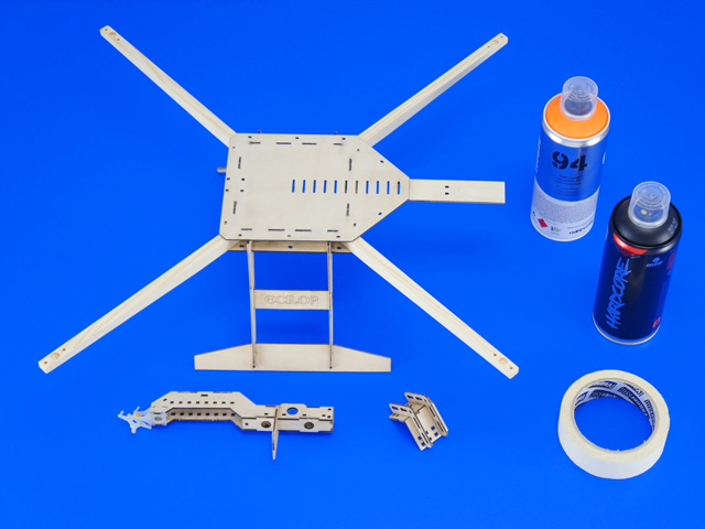
This file contains a list of frame components and vectors for cutting out individual parts:
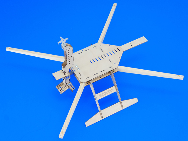
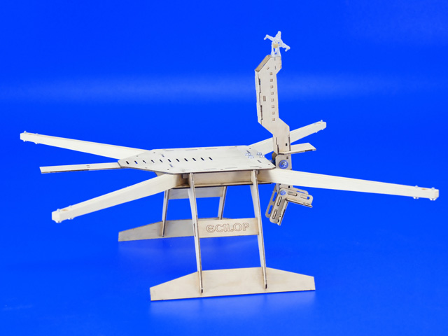
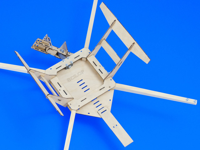
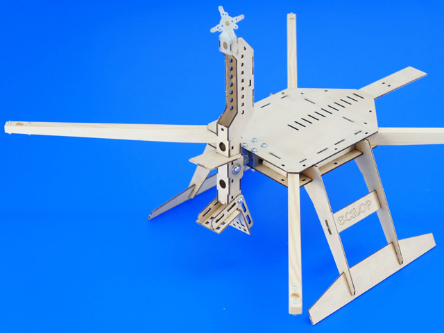
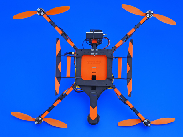
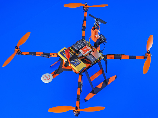
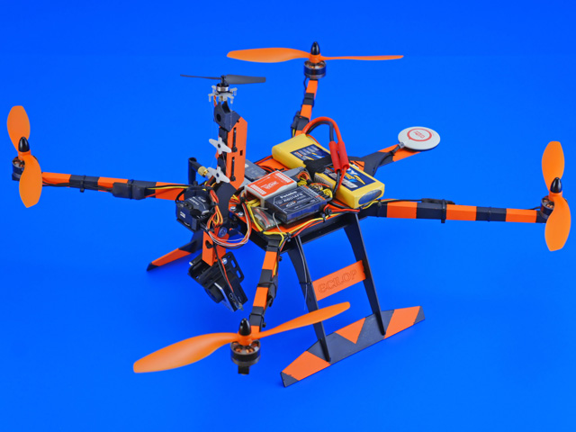
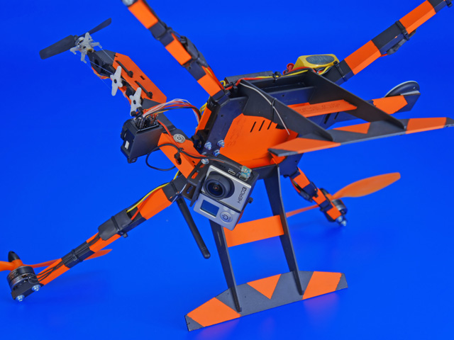
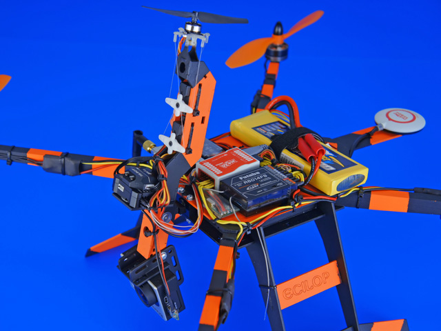
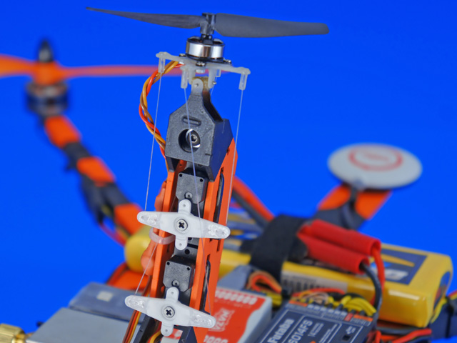
Frame assembly. Parts of the frame are first assembled and then glued together with the "Thin" Super glue. The liquid glue is applied to the joints and fills the seams, reliably fastening them in their positions. 1. Glue the engine pillars to the central frame. 2. Glue the reinforcement ribs to the central plane. 3. Glue the lower plate of the central frame. 4. Glue the GPS receiver platform. 5. Assemble the chassis pillars. 6. Glue the chassis to the central frame. 7. Assemble and glue together the balance beam. 8. Assemble and glue together the camera mount. 9. Insert the axles into the crossmember axle fixation holes (engine mount). 10. Assemble and glue together the engine mount. 11. Insert four tubes into the engine mount. Cut the tubes on the axle installation level. 12. Glue together the universal joint (U-joint). 13. Assemble the axle unit. 14. Install the bearing fixtures onto the central frame. 15. Glue the bearings of the "roll" axle using green (high strength) thread lock glue. 16. Glue the bearings of the "tilt" axle after the installation of the camera hanger. 17. Cover the assembled wooden elements with varnish or paint them. Equipment installation. 1. Use sandpaper to balance all the propellers. 2. If the small motor has rigid and breakable wires, replace them with softer ones. 3. Install the motor onto the engine mount. 4. Fasten the servo using glue and straps. 5. Fasten the speed controller. 6. Pull the fishing line through the tubes on the opposite ends of the engine mount. 7. On the walking beam of the servo mechanism, find holes with the same distance as on the engine mount. 8. Tension and glue the line on the servo arm. 9. Level the servo arm, the engine mount and glue the line to the inner surface of the tubes. 10. Install the camera mount and the camera. The camera can be pointed forward or downward. 11. Look for the most suitable positions for additional equipment on the balance beam to preserve the overall balance. Install an additional equipment platform on the balance beam, if necessary. 12. Put the copter on a side. Move the equipment around the mean for preliminary balancing. For accurate balancing, glue or screw down additional weights. 13. Install the copter onto a landing skid. For precise balancing, move and tilt the camera mount back and forth. 14. Move the camera sideways for precise balancing. Tighten the camera strap after balancing. 15. Install the engines, speed controllers, the flight controller and receiver. 16. Turn the air engine on the beam to 50% of its power. Find such a position of the main battery, where the center of mass of the copter is in the center of the frame. 17. Configure the onboard equipment. Follow the manufacturers’ manuals. 18. Check the balance of the beam in each direction once again. Make sure all the straps are tightened. Wires must not obstruct the tilting of the beam. Controlling the camera mount. Example 1. The copter and the camera are controlled by a single person. Controlling the camera mount. Example 2. The drone and the camera are controlled by two persons. The camera is more stable during maneuvering, but may tilt sideways from its horizontal position. The pilot controls the drone by looking at it from the side. The operator controls the camera using the video feed sent from the drone. In order to turn the drone together, two remotes must be connected in the trainer/trainee mode. The following equipment is installed on the balance beam: a separate battery, a separate control receiver, two gyroscopes and a video transmitter. The camera mount is not connected to the copter with any wires. The gyroscopes operate in the AVCS mode (Heading Hold). Follow the manufacturer's instructions when configuring the gyroscopes. In windless conditions and during hovering, it is recommended to reduce the RPMs on the beam engine to under 50%. This will provide a higher recording quality. RPM's should be increased in windy conditions. The beam speed controller uses the smooth start and "Governor" modes Additional equipment required: Engines with a static thrust of 500-700h, 19mm mounting holes, 4 units Propellers, 10" max, 4 units Speed controllers, 10-15A, 4 units A flight controller for the quad-copter (no special requirements) Battery, weigh 200-400g Remote control, 7 channels or more An engine with a static thrust of 30-90g, 10mm or R8.5mm mounting holes Propeller 2510 or 3020 speed controller 3A Servo gears for the copter's tail, max width 13mm, 2 units Gimbal Stabilization controller Action video camera
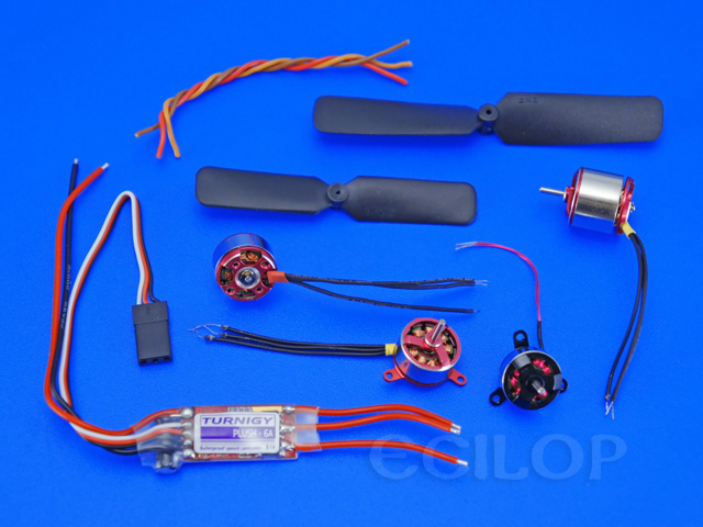
Sample package Frame: Ecilop Eco V1306 Motors: MT2206-23 Propellers: Slow Fly 8x4.5 Speed controllers: T-motor 10A Fligh controller: DJI NAZA Receiver: Futaba R6208 Battery: 4000mA/h, 3S, 25C Power wires: AWG16 Fifth motor: A05 2900rpm/v Propeller: 2510 Speed controller: Plush 6A Servo: MKS Ds480 Gyro: Turnigy Mini MEMS Camera: GoPro-3 Videolink: 5.8gHz, 200mW An example of controller settings In the example below, the drone and camera are controlled by a single person. The gyroscopes of the ZYX-GS controller are not used due to the insufficient of gain. The order of module connection is as follows: Receiver Futaba / Camera Gimbal Stabilization System ZYX-GS / Gyro Turnigy MINI MEMS / Servo MKS Ds480 Gyro Turnigy MINI MEMS, Settings: Camera Gimbal Stabilization System ZYX-GS, settings: Speed Controller - governor mode, 70% throttle
Aleksey Zaitsevsky, 2013, http://www.myresearch.company |