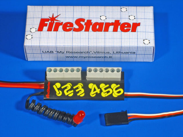   
Launch of smoke, comets, fountains and rockets by R/C models The device "FireStarter" is developed for remote control of electric igniters. Up to six electric igniters can be connected to the device. For connecting the device, one of free channels of a standard receiver of the on-board R/C system shall be used. Igniters can be activated both by a choice and successively. The device issues a high level reliability and safety required on working with pyrotechnics.
Video: FireStarter on the ground and on water. FireStarter on aircraft models.
Connection of the device
1. Connect the device to a free channel of the on-board receiver controlled by a switch or a button on your control panel. 2. Connect the power supply cables to the on-board battery according to the scheme. You may use the main battery or an individual battery. The recommended type of an individual light battery: two sections of Li-po accumulators with the summed voltage of 7.4V, capacity 900 mA/h, current 15C. Power supply from the battery will be used on an activation of an igniter only. Observe the polarity! 3. Fix the device on the body in an accessible point. For fixing, a double-side scotch and a hoop should be used. 4. Fix the external indicator. 5. For checking up operation of the device, the igniters may be replaced by lamps with the voltage exceeding the voltage of the battery. Or by nothing. 6. Switch-on the transmitter 7. For the chosen channel, set two replaceable positions +100% and -100% (in some transmitters – 0% and 100%, where the neutral value is 50%, not 0%). If a control stick is used instead of a switch, switching will take place in the neutral position. 8. Switch-on the on-board devices. 9. The red indicators of igniters should flash in turn. If all red indicators are lighting, invert the control channel of the transmitter. If the red indicators still are lighting permanently or the device does not switch on, disconnect the on-board power supply and check up a correctness of the connection. Control of igniters 1. The waiting mode 2. Choosing an igniter 3. Readiness for start 4. Ignition of an igniter 5. Safety. Any operation will be stopped, if:
The safety measures 1. One may be involved in pyrotechnical works after the relevant training and certification of qualification. More detailed information is available in the local fire-prevention service.
The technical data The feeding voltage from the receiver - 4.5-5.5V
What electric igniters can be used? Igniters designed for festal pyrotechnics, igniters for launching models of rockets, professional pyrotechnics with built-in igniters, or homemade igniters. Sets for making igniters at home are available in trading nets and, otherwise than ready-made igniters, can be sent by mail. Sometimes igniters are sold under the name "electric matches". What kind of wires should be used for connecting of the fuses? The wire with the section area of 0,2...0,5 mm² (0,5...0,8 mm in the diameter) should be used for connecting of the fuses. Please, don't use the thin wires, if the fuse needs more than 3A of el. current or if the length of the wire exceeds 1 meter. The short wires with the section area of 0,5...1mm² (approximately 1 mm in the diameter) should be used for connection to the battery. What the tension of the battery should be available? The tension of 5...12V is acceptable in most of the cases. A higher tension (12...15V) may be needed, if the fuses with long wires or with high own resistance are used. Such situation is possible when the fuses, meant for the rocket models, made out of long nichrome wire and with a long cable, are used. If the voltage is insufficient, then the fuses are not activated and remain undamaged. A lower tension (3,6...6V) is necessary for the fuses with a lower resistance. As a rule, these are the home-made fuses, produced out of a very short nichrome wire and short cables. Such fuse is detected by the device as the defective one. Moreover, if the voltage is higher, then the fuse may burn without ignition. The el. current, meant for such fuses, may be limited by connecting them in turn via the resistance of 1 Ohm 10 W. The green indicator is lighting; however, the igniter is not activated. Why? Probably, there is short-circuiting in the installation or the igniter itself. It is also possible that the igniter requires current exceeding 10A. Check the connection of the igniter and replace the igniter itself. The red LED's blink all together; activation of igniters does not occur (?) Certain receivers generate the control signal with the altered period of recurrence. The device accepts such signal, as the one, which does not meet the standard. This problem occurs only, if the first version of the device is used; the versions, which are being manufactured nowadays, receive such signal normally. Why the device "FireStarter" fails to operate with certain fuses? I have in mind the self-made fuses. Some companies sell the half-finished fuses with a short nichome thread, which should be soldered to the wires and coated with the combustible substance. The current for ignition of these fuses is less than 5A. The problem is that their resistance is too low. Prior to ignition the consumed current may be higher by ten times. This impulse may be very short, but protection of the device "FireStarter" goes off quicker. The current is calculated according to the Ohm's law, i.e. I=U/R. Resistance of good igniters should not be less than 1 Ohm. If resistance of the igniter is 1 Ohm and tension of the feeding is 10V, then the first impulse of the consumed current will make 10A. In such case the device "FireStart" will switch off quicker than the nichrome thread will burn off in spite of the fact that only 3A are necessary for its burning off. Why only some fuses were activated and the rest ones failed? If, in the course of activation of all the fuses in turn, the device turns suddenly into the expectancy regime, it means that the short circuit is detected in one of the fuses. Seeking to activate the fuses, which follow the defective one, it's necessary to choose manually the fuse, which follows the defective one. Is it possible to connect more than one igniter to a single channel? Yes, it is; however, if the summed current exceeds 10A, the device will response to it as to short-circuiting and will transfer to the waiting mode; the igniters will remain undamaged. Usually, the actuating current of industrial igniters is about 3A, i.e. in most cases, a parallel connection of two igniters is possible. The readiness period of 10 second is insufficient. What could be done? The limit of 10 second was set for the purpose of safety. However, on activation of one of the igniters, the 10-second period is not valid. You can replace the first igniter by a lamp and use pyrotechnics starting from the second igniter. Then activate the first channel and remain it activated. The lighting lamp means that the next switchover will cause an activation of the igniter. In such a way, it is possible to maintain the mode of readiness for the whole period of the presentation. However, it is not recommended. The readiness mode may be also interrupted because of RF noise or defected igniter. How the weight of the device can be reduced? The weight of the device without the cabinet, without the wires and the removed screw terminals is 6 g. So as to reduce the weight, it's possible to use shorter wires and lighter connectors, meant for connecting of the fuses. If You use a separate battery for ignition of fuses, then the easiest variant would be as follows: 1 section of the Li-po accumulator, the capacity of which is 300mA and the el. current output is 10C. The fuses, which need the tension of 3V and the el. current of 3A for ignition, should be used. What will occur, if the device gets into water? The device will fail executing the command for start; a damage of the device can occur as well. Avoid getting of moisture into the device and never switch-on the device with traces of moisture! Is a self-actuation of igniters possible? It seems to be slightly credible. It can occur, if both supply switches in the scheme of the devices blow-out and remain short-circuited. All devices are inspected before sales; however, a defect may appear in the process of exploitation. If green indicators of connected igniters are lighting on activation of the device in any mode, this means that a damage of the positive supply switch takes place. If one or several igniters automatically actuate on a transfer to the mode of readiness, this means that a damage of the negative supply switch takes place. Using a damaged device is dangerous! Schematic:
PCB: Aleksey Zaitsevsky, 2008, http://www.myresearch.company Tags: FireStarter, fire starter, onboard smoke, igniter activation, ignition controller, electric match, electric matches, onboard fire show, shooting from model, pyrotechnics for models, fire comets, fire fountains, rockets on helicopter, onboard firing, remote activation of igniter, remote ignition, guns on models, guns for models, remote controlled ignition, radio controlled fire, remote explosion, bombing simulation, rocket launching, R/C firing, firing device, firing system, war simulation, toy guns. |