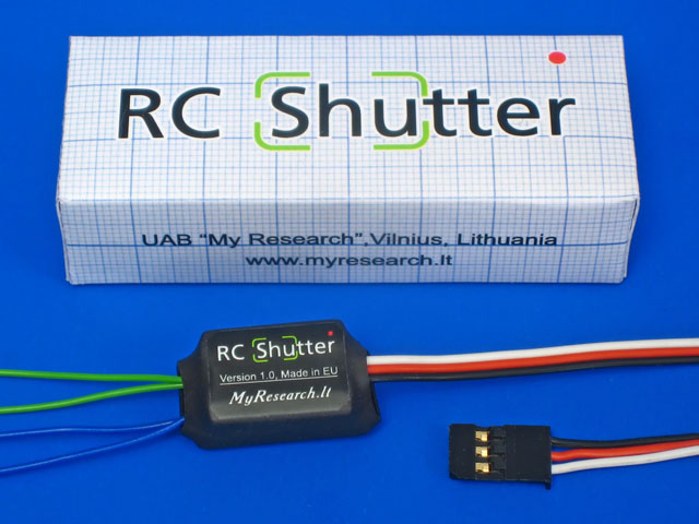    
The three-positional double switch, which is controlled via one control channel.
The regime of operation of the device depends upon the position of the switch at the moment of switching the board feeding on. Switching in the regime of the consecutive switch-off
Switching in the regime of the separate switches
Switching in the regime of the triggers.
Recommended settings for the control panel: The technical data Max. Consumption Current - 20 mA Max. Switching Voltage - 200V Max. Switching Current - 1A Max. Switching Power - 20W Weight - 10 g Sizes - 28x15x12 mm The device can control two buttons of the camera; if four buttons must be controlled, two devices and two channels of the remote control must be used. Video:
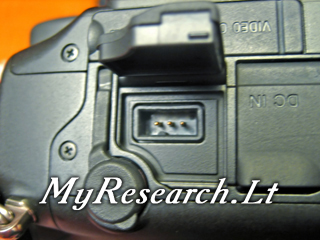
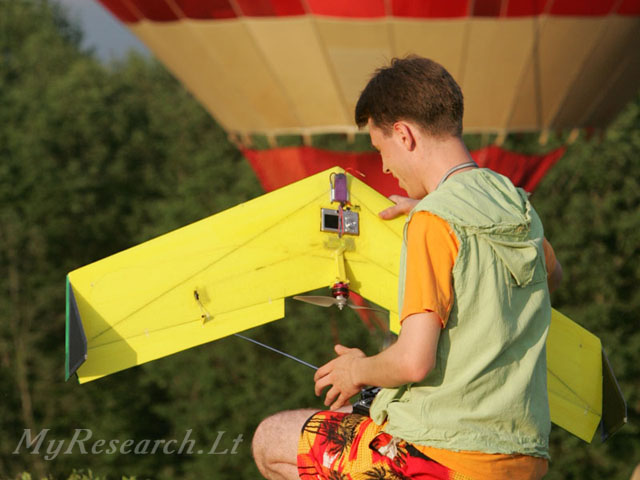
The method of control of the photo/video-camera, which is installed on the radio controlled model, is described in this article. Some cameras are provided with special terminals for connecting the external control panels. For example, certain cameras Sony are provided with such terminals:
The device RC Shutter can be connected to such terminals. The cable with the plug from a common servo-mechanism will suit for connection. One blue and one green wires of the device RC Shutter are to be connected to the third contact. The second green wire is to be connected to the second contact, whereas the second blue wire is to be connected to the first contact. For Pentax cameras, a 2.5 mm stereo plug is used; the wiring is shown in the image:
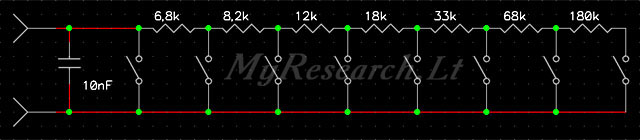
The scheme of some remote control panels resembles the one, which is submitted below.
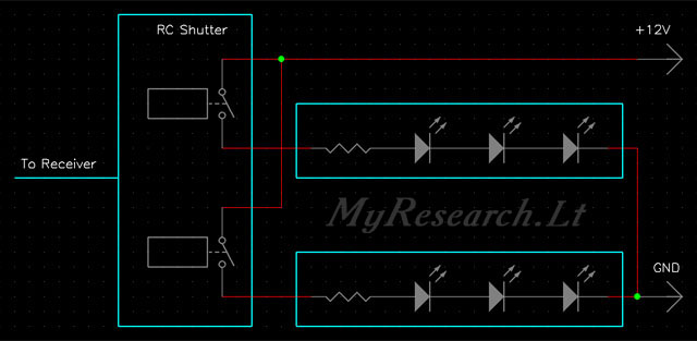
The number of buttons and resistance rates may differ. The device RC Shutter is connected instead of the buttons. If no remote control panel is available for the photo-camera, the outlets of the device are connected in parallels to any buttons inside the camera. The device RC Shutter allows controlling two functions via one control channel. The scheme, showing operation of the device, is submitted below. As regards this scheme, the device is used for controlling the board lights of the model.
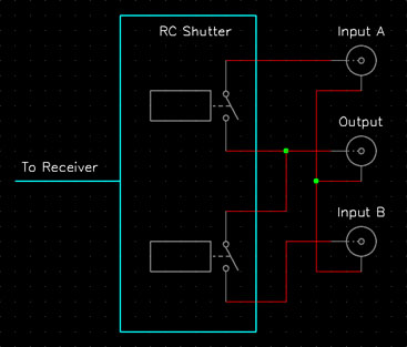
Two chains of the illuminating elements can be independently controlled. It is possible to control the light emitting diodes, lamps, motor, siren or photo-camera as well as to switch any digital or analogous signals. The connection scheme, which allows switching the view, which is being transmitted to the operator, is submitted below.
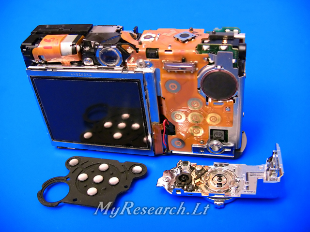
For example, one video-camera, assigned for navigation, and one controlled video-camera, assigned for photo-making, can be installed on the model. The example of connection to the photo-camera's scheme. The universal method of the wire connection will be described further on. Such method requires attentiveness and certain skills, but it allows controlling any function of any digital camera. Firstly, the battery must be disconnected from the photo-camera and afterwards the case must be removed.
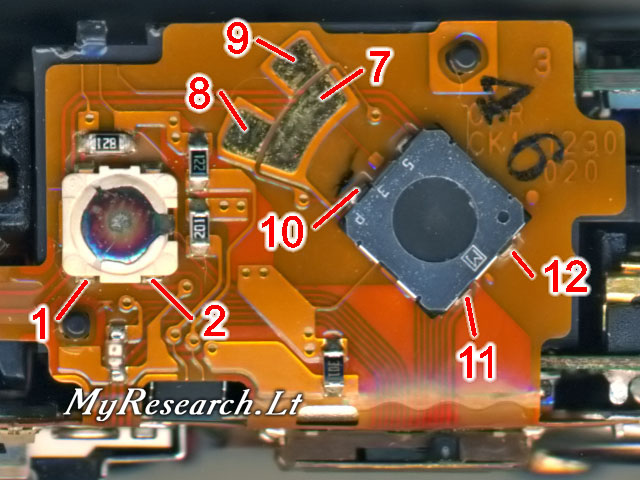
It is convenient to use thin wires and a small soldering iron, aiming at connecting to the contacts. It is sufficient to connect the outlets of the device RC Shutter to the contacts of the button. The same method is used for connecting the contacts to the button, assigned for switching the camera on (1, 2).
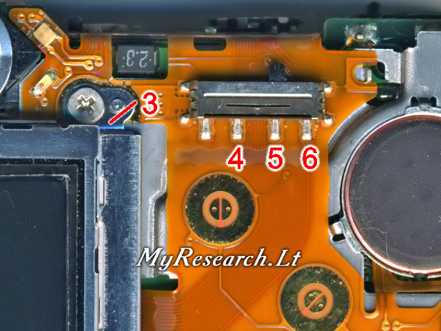
Seeking for connecting to the switch, it is necessary to ascertain which contacts and in which regime are closed and which contacts remain unused. The electric tester is necessary for this purpose.
If the resistance between the contacts is less than 100 Ohms, it means that they are closed. If the resistance between the contacts and the metal screen of the scheme (3) exceeds 500 kOhms, it means that this contact is not being used. As regards this particular example, the second (4) and third (5) outlets of the switch are closed in the regime "video", whereas the third (5) outlet is not being used. The second (4) and fourth (6) contacts are closed in the regime "photo". It means that the switch must be left in the position "video", whereas the outlets of the device RC Shutter must be connected to the second (4) and fourth (6) contacts. The contacts, which are being closed with the help of the transfocator's lever, are well seen (7, 8, 9). It is desirable to connect the RC Shutter so that the wires do not derange this lever's operation. The button of focusing and shutter has two positions. It must be ascertained with the help of the tester, which contacts are closed after having pressed them slightly (10-11) and which contacts are closed after having pressed them more strongly (10-12). The RC Shutter is connected in parallel to these pairs of contacts.
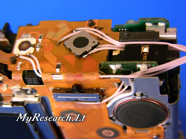
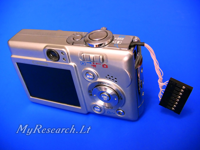
The tester can be used for ascertaining which contacts of various buttons and switches are closed in between. It is possible to connect such common contacts with the help of one thin wire; afterwards several outlets of the RC Shutter can be connected to this wire. As regards this particular example, the thin wires are led out via the body of the photo-camera outwards.
Availability of the terminals allows disconnecting the photo-camera from the control system. The photo-camera, disconnected from the control system, operates as earlier; all its buttons and switches function.
Schematic:
PCB: Aleksey Zaitsevsky, 2010, http://www.myresearch.company |